A single blown globe can knock out an entire string of fairy lights—because in a series circuit, all components share one continuous path, and a break anywhere stops current flowing everywhere. This resource builds on current, voltage and resistance to explore how series circuits behave, including how voltage is shared across components and how Kirchhoff's laws help us analyse them.
Kirchhoff's laws
The principles of conservation of charge and conservation of energy can be used to establish two very important rules that apply to all electric circuits. These are called Kirchhoff's laws.
Kirchhoff's current law
Kirchhoff's current law states that in any electrical circuit, the sum of all currents flowing into any point is equal to the sum of the currents flowing out of it.
For example, if at any junction of three wires, there is \(2\,\text{A}\) flowing in on one wire and \(3\,\text{A}\) flowing in on another, then there must be a current of \(5\,\text{A}\) flowing out on the third.
Currents flowing into the point will be positive (\(+\)) and those flowing away from the point negative (\(-\)). As a result, Kirchhoff's current law is sometimes abbreviated to 'the sum of all currents at a point is zero.'
Kirchhoff's voltage law
Kirchhoff's voltage law states that the total potential drop around a closed circuit must be equal to the total voltage (EMF) in the circuit.
For example, if we know that a torch battery supplies a voltage (EMF) of \(3.0\,\text{V}\) and we measure a \(2.8\,\text{V}\) potential difference across the bulb, there must be a \(0.2\,\text{V}\) drop somewhere else in the circuit – possibly across the switch contacts if they are a little dirty.
Connecting circuits in series
No matter how complex a circuit, it can always be broken up into sections in which circuit components are combined either in series or in parallel. In series, components are connected one after another in a single path so the same current flows through each component.
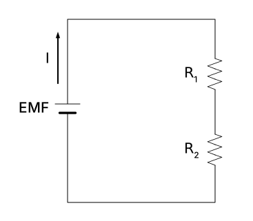
In this circuit, the sum of all the potential differences across the resistors \(V_{1}\) and \(V_{2}\) will equal the potential difference, or voltage of the supply \(V\). The voltage of the battery is therefore given by:
\[\text{EMF} = V = V_1 + V_2\]
For resistors in series, the equivalent resistance \(R_{\text{EQ}}\) is equal to the sum of the individual resistances.
\[R_{\text{EQ}} = R_1 + R_2\]
The current \(I\) leaving the battery must flow through both \(R_1\) and \(R_2\), so the current in a series circuit is the same at every point. For resistors connected in series, the same current must pass through each resistor.
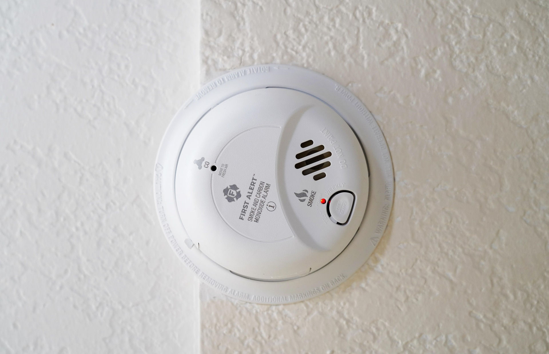
In addition to fairy lights, other examples of series circuits include a simple torch and a smoke detector circuit.
Example – measuring electricity in series circuits
Two pieces of nichrome wire (as used in heater elements) have resistances of \(\mathbf{10}\,\Omega\) and \(\mathbf{20}\,\Omega\).
What current would flow through them, and what power will be produced in them, if they are separately connected to a \(\mathbf{12}\,\textbf{V}\) battery?
The current will be given by \(I=\dfrac{V}{R}\). For the two wires separately, the currents will be \(\dfrac{12}{10}=1.2\,\text{A}\) and \(\dfrac{12}{20}=0.6\,\text{A}\).
The power is found using \(P=VI\). For the two wires separately, the powers will be \(12\times1.2=14.4\,\text{W}\) and \(12\times0.6=7.2\,\text{W}\).
If they are connected in series, what is their total resistance?
When connected in series, the total resistance will be:
\[\begin{align*} P & = VI \\[6pt]
& = 12\times0.4\\[6pt]
& = 4.8\,\text{W}\end{align*}\]
Exercise – measuring electricity in series circuits
Shiori has found a point in her car where four wires are attached together. She finds currents of \(+2.5\,\text{A}\) and \(+1.0\,\text{A}\) in two of the wires, and \(-4.2\,\text{A}\) in a third. \(+\) indicates current travelling into the point and \(-\) indicates current travelling out of the point. What is the current in the fourth wire?
\(+0.7\,\text{A}\)
Two torch bulbs are placed in series with each other and a \(4.5\,\text{V}\) battery. The current through one is found to be \(0.25\,\text{A}\) and the voltage across it is \(2.1\,\text{V}\).
What is the current through the other bulb? Give your answer in \(\text{mA}\).
What is the voltage across the other bulb?
\(250\,\text{mA}\)
\(2.4\,\text{V}\)
Marcos has bought two \(12\,\text{V}\) headlights for his truck but finds that it has a \(24\,\text{V}\) battery. He decides that the simplest way to overcome the problem is to wire them in series.
Will the headlights work correctly?
Do you see any problems with this scheme?
Yes. In series, the \(24\,\text{V}\) split equally across the two identical \(12\,\text{V}\) headlights, so each receives its rated voltage.
Yes. If one of the headlights blows, then the other one will turn off as they are arranged in series. Losing both headlights when only one fails presents a significant safety concern.
Two equal resistors are placed in series and found to have a combined resistance of \(34\,\Omega\). What is the resistance of each one?
\(17\,\Omega\)
A \(10\,\text{V}\) power supply is used across two separate resistors. The current through one is found to be \(0.4\,\text{A}\), and through the other \(0.5\,\text{A}\). When they are combined in series:
what current will flow through them? Give your answer in \(\text{mA}\).
what is their effective resistance?
\(222\,\text{mA}\)
\(45\,\Omega\)
A \(400\,\Omega\) resistor and a \(100\,\Omega\) resistor are placed in series across a battery with a voltage (EMF) of \(5\,\text{V}\).
How much current will flow from the battery? Give your answer in \(\text{mA}\).