Electrical drawings
Ladder diagrams
A ladder diagram is a form of circuit diagram. They are mostly used to represent control logic circuits but can also be used to represent hard wired circuits. Two parallel lines are drawn representing the two sides of a supply circuit. Between the parallel lines 'rungs' are drawn to represent control circuits.
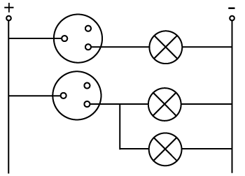
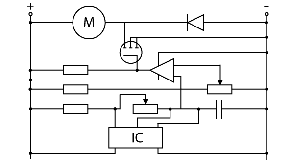
Two sample ladder diagrams are shown below:
- Simple diagram showing a light switching circuit. A lighting circuit would not normally be represented by a ladder diagram.

Simple ladder diagram
- A more complex ladder diagram showing motor control.

Complex ladder diagram


