Electrical drawings
Wiring diagrams
A wiring diagram is a more realistic representation of an electrical installation than a circuit diagram. The wiring diagram shows the terminals/connectors on components, the cabling between these connectors, links and bars. Each wire/cable is identified through the use of colours and/or numbering. The wiring diagram does not show how individual components operate.
A wiring diagram is used:
- when the installation is wired in the first place
- when a component in the circuit is replaced
- as an aid for fault finding.
If you have the task of wiring an installation and are supplied with a circuit diagram only, then you should create a wiring diagram also. The way to do this would be to first draw blocks to represent each component. Indicate all of the connectors and then draw in the cable and conductor connections between these connectors as you run the wires.
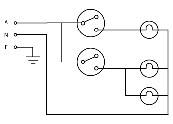
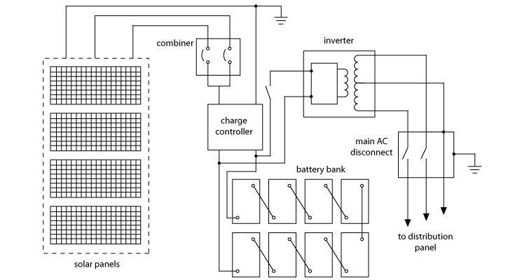
Two sample wiring diagrams are shown below:
- Wiring diagram showing a simple light switching circuit.

Simple wiring diagram
- A more complex wiring diagram showing a solar panel system.

Complex wiring diagram


