Architectural drawings
Symbols
Standard graphical symbols are used on architectural drawings to represent specific items. Using standard symbols ensures that anyone who knows the standards can interpret the drawings correctly. Architectural drawings (floor plans) use symbols to represent features of a building such as:
- swinging doors
- sliding doors
- windows
- shower recesses, etc.
Electrical components are also represented on floor plans using Australian Standard symbols. (AS 1102.111:1997 Graphical Symbols for electrotechnology documentation Part 111: Architectural and topographical plans and diagrams.) A sample of these symbols is shown below:
Select a title to see related symbols
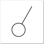
Switch - general
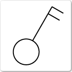
Switch - two pole
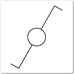
Switch - two way, single pole
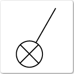
Switch - with pilot light
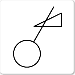
Switch - with dimmer
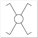
Switch - intermediate
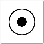
Switch - push button
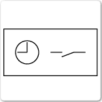
Time switch
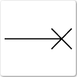
Lighting outlet position
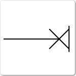
Lighting outlet on wall
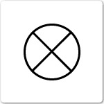
Lamp - general
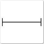
Fluorescent lamp - general
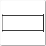
Fluorescent lamp - three tubes
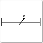
Fluorescent lamp - five tubes
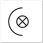
Projector - general
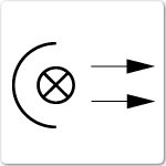
Spot light
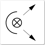
Flood light
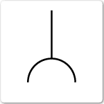
Socket outlet (power) - general
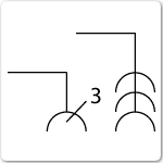
Multiple socket outlet(power) - 3 outlets shown
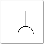
Socket outlet (power) - with shutter
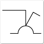
Socket outlet (power) - single pole switch
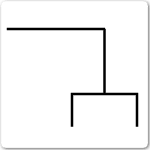
Socket outlet (telecommunications)
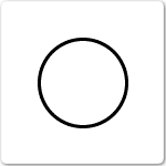
Box - general symbol
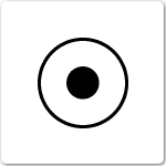
Connection or junction box
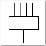
Distribution centre, five wires
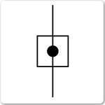
Consumer's terminal
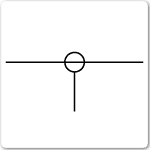
Subscribor's tap-off, single tap-off line
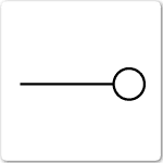
System outlet
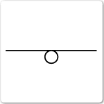
Looped system outlet
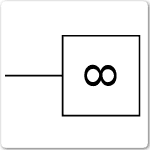
Fan
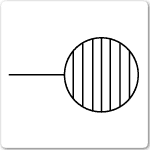
Water heater
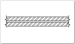
Wall - Cavity brick
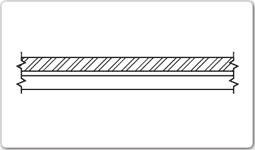
Wall - Brick veneer
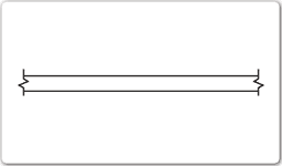
Wall - Timber stud
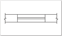
Window - In cavity wall
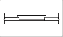
Window - In single wall
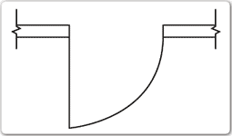
Door - Swing single
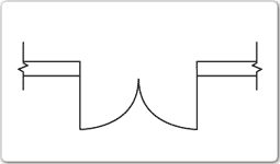
Door - Swing double
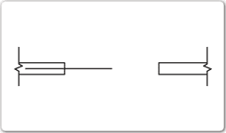
Door - Sliding into pocket
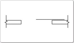
Door - Sliding exposed on wall


