

Architectural drawings
Scales
Drawings are done to a scale. This means that standard fractions are used in relation to the actual size of the object being drawn and the dimensions used on the diagram. Architectural drawings are done in scales that are smaller than the real size. Floor plans are commonly produced at 1/ 50th (1 to 50) or 1/100th (1 to 100) of their actual size. Site plans are often drawn at 1/200th (1 to 200) or even 1/500th (1 to 500) of actual size.
A scale of 1 to 100 is indicated on a drawing using the code 1:100. This can be interpreted as follows: 1 centimetre (0.01 metre) measured with a ruler on the plan would need to be multiplied by 100 to give the actual size of 1 metre. So on a 1:200 scale plan, if you measured a wall length as 1 centimetre the actual length of the wall would be 2 metres.
Mechanical drawings at times are drawn to actual size (1 to 1) or even enlarged (2 to 1). These scales would be indicated on the drawing as 1:1 and 2:1.
The scale is shown on the drawing, usually in the title block of the drawing. Sometimes different parts of a drawing are at different scales. This will be indicated next to each drawing.
You need to be aware of the scale, and you need to be able to convert measurements from a drawing to actual size. If the actual dimensions are not shown on the plan from the scale, then using a ruler you can work out the dimensions, eg if you had to lay a conduit diagonally under the concrete slab for a new building, you could work out the length required by measuring from the plan.
The photo below shows measuring diagonally with a ruler from a wall corner to a wall corner on a site plan.The measurement on the ruler is 78 millimetres ( 0.078 metres). The scale is 1:200. Therefore the actual size would be 15.6 metres (0.078m X 200).
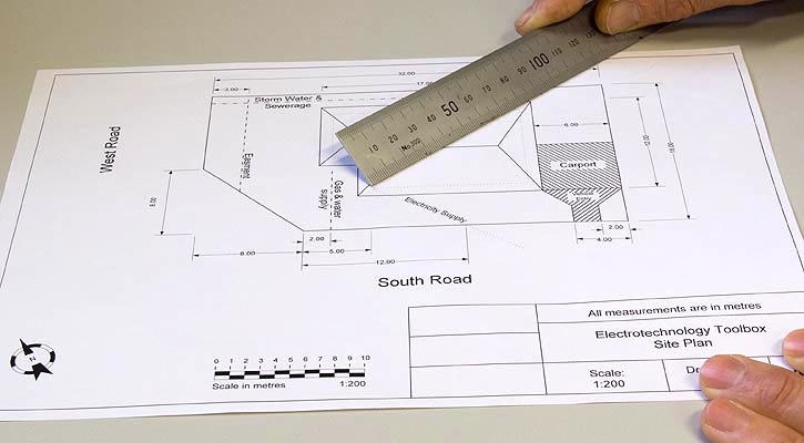
Measuring on a site plan