Mechanical drawings
Views
Mechanical drawings can be displayed with a number of views. The two that would be most common in the electrical trade are:
- orthogonal projection
- isometric projection.
Orthogonal projection
These drawings are the simplest drawing to interpret and are commonly used. They generally show the 'faces' of an object from one of up to six views:
- front (looking directly at the front face of the object); view A
- top (looking down on the top face of the object); view B
- left side (looking towards the left face of the object); view C
- right side (looking towards the right face of the object); view D
- bottom (looking up at the bottom face of the object); view E
- back (looking at the back face of the object); view F.
For most jobs three views, A,B, and C, are sufficient to give all necessary detail. The more complex the fabrication job the more views that are used.
For fabrication of a simple object, eg a toolbox, only a top view may be necessary. This would be to show the cutting and folding dimensions needed on the sheet metal.
There are two different ways that orthogonal projection can be drawn:
- first angle projection
- third angle projection.
Orthogonal projection mechanical drawings need to show which of these projection methods are being used. There is a standard symbol for this purpose.
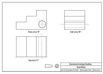
First angle projection
When the left face is drawn, it's drawn sitting to the right of the drawing of the front face. See the following example.
Select the image to view at full size (Word 29kb).
The projection symbol used to represent first angle projection shows two drawings of a solid cone with the point cut off. What you would see when looking at the cone from the left is drawn sitting to the right of the drawing of the front face of the cone.
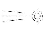
First angle projection symbol
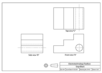
Third angle projection
When the left face is drawn, it's drawn sitting to the left of the the drawing of the front face, see the following example.
Select the image to view at full size (Word 29kb).
The projection symbol used to represent third angle projection shows what you would see when looking at the cone from the left, drawn sitting to the left of the drawing of the front face of the cone.
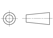
Third angle projection symbol
AS 1100 recommends the use of third angle projection.
Isometric projection
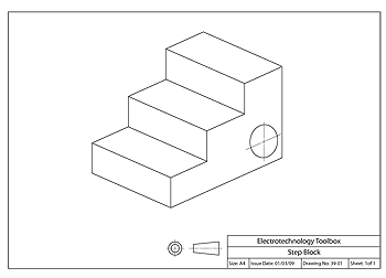
This is another mechanical drawing view that you, as an electrician, may need to use when fabricating an object. The object is shown as if looking down onto it from one corner. The one drawing can show the same information as the top, front and side orthogonal drawings.
Note: An isometric drawing is not drawn in perspective. Sides and lines do not taper as you would see if you were looking at the real object.
Select the image to view at full size (Word 31kb).


