Electrical principles - Measurement
Meters
There is a range of meters used for measuring various electrical quantities. These meters are often expensive and delicate pieces of equipment, so they should always be handled with care and used according to the manufacturer's instructions.
Meters are available with two different forms of readout:
- analogue – readout on a graduated scale with a pointer operated by a magnetic field
- digital – readout on a digital screen.
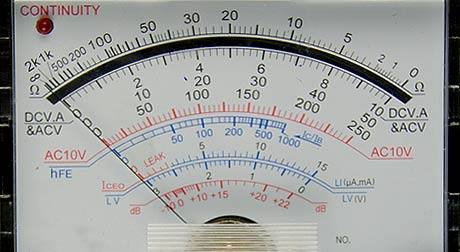
Analogue display
An analogue meter must be positioned correctly. If placed on its side or an angle, the pointer could be affected by gravity and give an incorrect reading.
When viewing the scale, position yourself directly in front of the scale. If viewed from an angle, you will get an incorrect reading – the greater the angle the more inaccurate it will be. This is because the pointer is separated from the graduation scale by a short distance. This is called the parallax effect.
An analogue meter must be checked for zero before being used. There is usually a zero set screw adjustment to ensure that the pointer starts on the zero calibration before measurement is taken. Any time you change scales when measuring resistance, you must always set the zero again.
Always connect meters with the correct polarity – black to negative and red to positive. Failure to do this could damage the meter, particularly an analogue meter.
Digital meters are difficult to read in direct sunlight. Most have a battery to supply power. Make sure that the battery is not flat and that you have a spare available.
The four most common meters are:
- voltmeter
- ammeter
- ohmmeter
- multimeter.
Voltmeter
A voltmeter is used to determine the voltage (electrical pressure) present at any point in a circuit.
Connecting the voltmeter across the battery measures the voltage present in the battery.
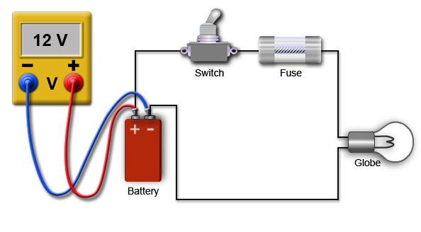
Measuring battery voltage
Connecting one lead of the voltmeter to the input side of a globe and the other lead to earth results in a reading of the voltage present at the globe. Voltmeters are mostly used to measure voltages across components. They are connected in parallel with the component.

Measuring voltage at the globe
Ammeter
An ammeter measures the amount of current flowing through a circuit.
An ammeter must be connected in series with the circuit. An ammedter has a very low internal resistance and must never be connected directly to a power supply without being in series with a load. The ammeter used must be capable of carrying the current that you expect to read.
To connect an ammeter, the circuit needs to be disconnected (broken) and the ammeter placed in series with the circuit.
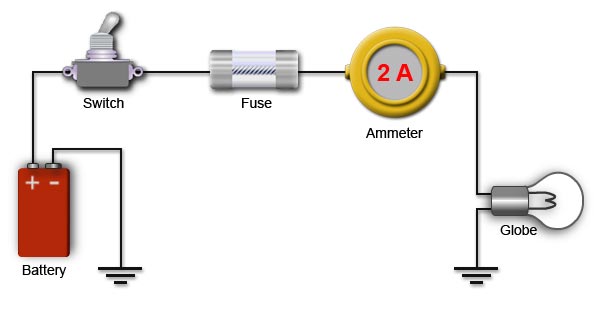
Measuring current flow
Ohmmeter
An ohmmeter is used to measure the amount of resistance in a component or section of circuit.
An ohmmeter has its own power supply. The circuit being tested must always be de-energised (turned off) when using the ohmmeter.
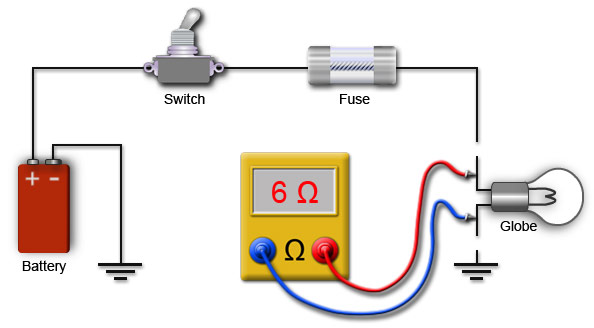
Measuring resistance of a globe
When using an ohmmeter:
- isolate the component or circuit section that requires measurement to ensure a correct reading occurs
- avoid touching the metal probes of the ohmmeter as this may lead to a false reading.
Warning
Failure to disconnect or isolate the component being measured from the power supply will cause damage to the ohmmeter.
Multimeter
A multimeter, as its name suggests, has multiple uses. Some of the quantities it can measure include voltage, current and resistance. Multimeters are available with analogue or digital readouts. Digital multimeters are commonly used as they give accurate results and are easy to read, except in direct sunlight.
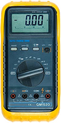
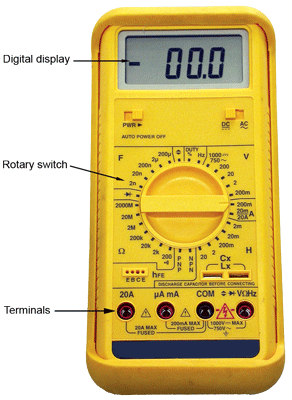
Multimeters
The two different multimeters shown can measure a range of electrical quantities including voltage (AC or DC), ohms, continuity, capacitance, frequency and current (AC or DC).
The rotary switch is used to select the quantity (and range) you wish to measure. The left side meter is auto ranging and the user needs only to select the type of quantity to be measured. For the right hand side meter, the user needs to select the electrical quantity as well as an appropriate range based on the value expected. It is best to start with a high range and then progressively rotate the switch to a lower range.
The test leads of the multimeter need to be connected into the meter in the appropriate positions. The black lead connects into the COM (common) position and the red lead into either V, A or mA position, depending on whether you are measuring voltage (V), resistance (Ω) or current (A or mA).
When testing a circuit with a multimeter, you need to connect the leads to the circuit appropriately depending on whether you are measuring voltage (V), resistance (Ω) or, current (A or mA). The connections are the same as for the voltmeter, ammeter and ohmmeter described above.


