Electrical principles - Circuits
Series/parallel
This circuit is a combination of the series and parallel circuits.
Some sections of the circuit are series and others are parallel. This can be in any number of combinations.
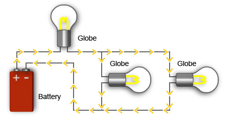
Globes connected in series/parallel
Electronic circuits and control circuits are examples of series parallel circuits.
To solve calculations related to series parallel circuits, the different parts of the circuit can be treated as sets. You can then solve each set separately and group the values for each set into one series circuit or parallel circuit, depending on the configuration.
To help do this you can redraw a circuit.
Below is an example of a series parallel circuit and the process of redrawing and calculating the equivalent total resistance for the circuit.
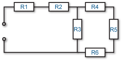
Series parallel circuit
The above diagram shows six resistors in series and parallel. With an understanding of current flow, you should be able to identify three resistance sets in the diagram.
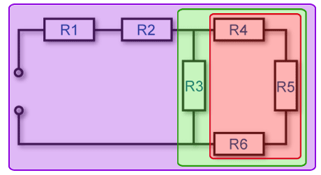
Circuit separated into three sets or areas
In the above diagram the three different sets of resistance have been identified using colour as follows:
- red (set one) is indicating resistors R4, R5 and R6 that are in series with each other
- green (set two) is indicating a parallel circuit with R3 in parallel with set one
- purple (set three) is indicating a series circuit consisting of R1, R2 and set two.
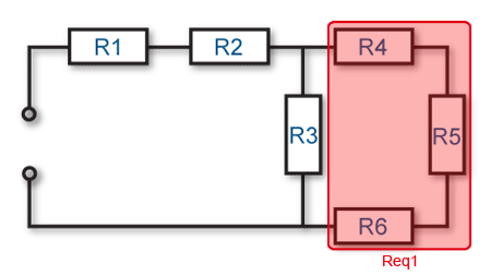
Calculating value of set 1
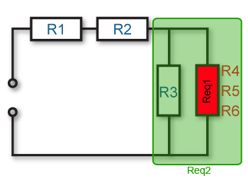
The innermost set of resistors (set one, red) R4, R5 and R6 are in series with each other, so they can be regarded as one resistor with a total resistance equivalent to:
Req1 = R4 + R5 + R6
Calculating value of set 2
The next set of resistors (set two, green) consists of R3 being in parallel with the series of R4, R5 and R6 (set one, red). This is equivalent to a resistor R3 being in parallel with a second resistor with the equivalent value R4 + R5 + R6 – represented by Req1 in the diagram above. Therefore set 2 can be regarded as one resistor with a total resistance equivalent to:
Req2 = (R3 x Req1) / ( R3 + Req1)
Calculating value of set 3
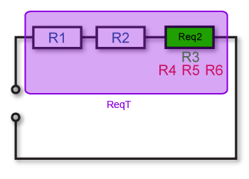
The final set of resistances (set three, purple) is a series and consists of resistances R1, R2 in series with the series parallel set made up of R3 to R6 . This is equivalent to R1 and R2 being in series with a third resistor having a value of (R3 x Req1) / ( R3 + Req1) – represented by Req2 in the diagram above. Therefore the total resistance of the circuit would be equivalent to one resistor with a value of:
ReqT = R1 + R2 + Req2


