Electrical principles - Circuits
Parallel

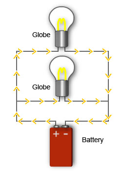
Globes connected in parallel
A parallel circuit has more than one path that current can flow on.
Removing or adding loads to a parallel circuit does not affect any other load in the circuit.
Most of the electrical circuits in a house, including the lighting and power points, are connected in parallel.
Each electrical load in a parallel circuit has the same voltage applied to it. This is because there is a direct path to the positive and negative side of the power supply.
The current flow through each load is determined by the resistance of the load.

Circuit diagram for three resistors connected in parallel
The total resistance in the circuit is less than any individual resistance in the circuit.
The more loads (resistors) placed in a parallel circuit, the greater the total current flow and the lower the total resistance.
The current flow through each individual resistor would be calculated using Ohm's law, eg I1 = V/R1
The total current flow would be equal to the sum of the current through each resistor.
Kirchoff's current law
Kirchoff's law states that the current flow from one side of a power supply must equal the current flow to the other side. Therefore, the total current flow can be shown with the following formula:
IT= I1+ I2+ I3...
Because each branch of the parallel circuit has a different current flow, a parallel circuit is know as a current divider.
Total resistance
We already know that current and resistance are the opposite of each other. If resistance increases then current decreases and if resistance decreases then current increases. In other words, they are the reciprocal of each other. In math terms the reciprocal of a number is one divided by that number, eg the reciprocal of two is one divided by two, so the answer is a half (1/2 or 0.5), a smaller number than the original.
From Kirchoff's law, we know that the total current flow would equal the sum of of current flow through each resistance in a parallel circuit. Kirchoff's law can be rewritten by substitution with Ohm's law (I = V/R), as follows:
VT/RT = V1/R1+ V2/R2 + V3/R3 etc
Since all of the voltages in a parallel circuit are equal, they cancel out so the formula can be written as:
1/RT = 1/R1+ 1/R2 + 1/R3 etc
This is known as the reciprocal formula and can be used for any number of resistors, of any value in a parallel circuit.
Example
In the above circuit diagram, if the values are:
R1 = 60Ω
R2 = 20Ω
R3 = 30Ω
What is the total resistance?
1/RT = 1/R1+ 1/R2 + 1/R3
1/RT = 1/60+ 1/20+ 1/30
1/RT = 1 + 3 + 2/60
1/RT = 6/60
RT = 60/6
RT = 10Ω
Power dissipation
The power dissipated in a parallel circuit is equal to the sum of the power dissipated in each resistance. From the section on power you know the formula:
P = VI
So the total power dissipated would be calculated as:
PT = P1 + P2 + P3 + ...
If you know the current flow through each of the resistors then you could use:
PT = VTI1 + VTI2+ VTI3
If only the individual resistance values and the voltage are known, by substitution you could use the formula:
PT = (VT2/R1) + ( VT2/R2) + (VT2/R3)
Example
In the above circuit diagram, if the values are:
VT = 20V
R1 = 50Ω
R2 = 20Ω
R3 = 100Ω
What is the total power dissipated?
P1 = VT2/R1 = 202/50 = 8W
P2 = VT2/R2 = 202/20 = 20W
P3 = VT2/R3 = 202/100 = 4W
PT = P1 + P2 + P3
PT = 8 + 20 + 4
PT = 32W
If the total resistance has been calculated, as in the example shown earlier, current can be calculated using Ohm's law. You can then use the power formula P = VI
Total resistance:
1/RT = 1/R1+ 1/R2 + 1/R3
1/RT = 1/50+ 1/20+ 1/100
1/RT = 2 + 5 + 1/100
RT = 100/8
RT = 12.5Ω
Total current flow:
I = V/R
I = 20/12.5
I = 1.6A
Total power dissipated is:
P = VI
P = 20 x 1.6
P = 32W


