Electrical principles - Circuits
Series circuit

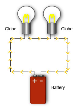
Globes connected in series
A series circuit has two or more loads connected, one after the other.
The current has only one path it can flow along.
An example of a series circuit is a set of Christmas tree lights. All the globes are placed one after the other.
There is only one path, so the current flow will be the same at any point in the circuit.

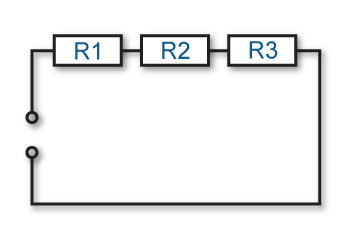
Circuit diagram showing three resistors connected in series
The total resistance in a series circuit will be equal to the sum of each individual resistance in the circuit.
The more loads placed in the circuit, the more resistance.
The total resistance for a series circuit is calculated using the following formula:
RT = R1 + R2 + R3
Kirchoff's voltage law

Voltmeter across each resistor in a series circuit
Kirchoff's law extends Ohm's law in relation to voltages across resistances in a series circuit. The total supply voltage will be equal to the sum of the voltage drop across each resistor.
Total voltage drop (VT) is calculated using the formula:
VT = V1 + V2 + V3
If both the current flow and each resistance value are known, then Ohm's law can be used to calculate the voltage drop across each resistor.
Eg:
V1 = IR1
Power dissipation
The power dissipated in a series circuit depends on the supply voltage applied to the circuit and the current flow in the circuit. The current flow depends on the total resistance of the circuit.
From the section on power you know the formula for power dissipation is:
P = VI
The power dissipated in each individual component depends on the resistance of the component. The total power dissipated will be equal to the sum of the power dissipated by each individual resistance. Depending on the values that are known, combinations of the power formula, as well as Ohm's law, can be used to calculate power dissipated (or any other unknown value).
Example
In the above circuit diagram, if the values are:
VT = 20V
R1 = 50Ω
R2 = 20Ω
R3 = 100Ω
The total resistance can be calculated as follows:
RT = R1 + R2 + R3
RT = 50 + 20 + 100
RT = 170Ω
What is the total power dissipated?
You could calculate the current flow and then calculate the power. Instead you could use substitution to get the formula.
In the formula, P = VI substitute the I with VT/RT to give the formula
PT = VT x VT/RT which is the same as
PT = VT2/RT
PT = 202/170
PT = 0.235W or 235mW


