Measuring resistance
Following are information and questions relating to insulation resistance (IR) testing.
Instructions:
For the five questions:
- choose the correct answer
- write down your answer.
Note:
- You can print this page and write your answers onto it.
1. What is the function of the insulation resistance (IR) tester?
- Measure resistance value of insulation.
- Determine the insulation value required for a given circuit.
- Measure conductor current draw capability.
- All of the above.
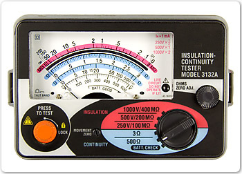
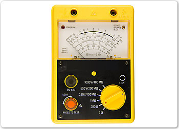
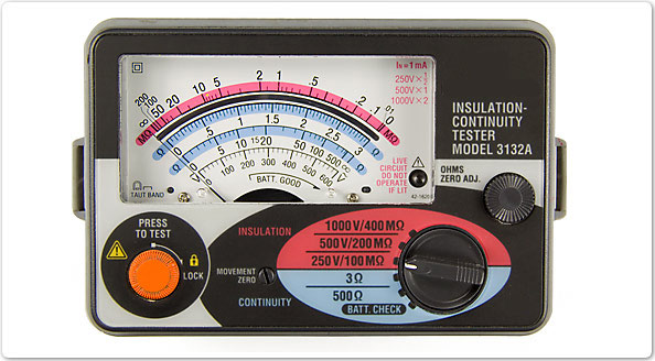
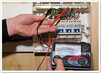
There are many types of insulation resistance testers. Below are two examples.
2. Why check the resistance of insulation?
- As a preventative maintenance task.
- To diagnose a fault in a circuit.
- To check performance against specifications.
- All of the above.
Insulation can deteriorate for a number of reasons including:
- age
- temperature extremes
- chemical contamination
- mechanical stress.
The IR tester can be used to determine the condition of insulation.
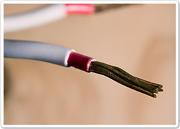
Areas of the IR tester are listed.
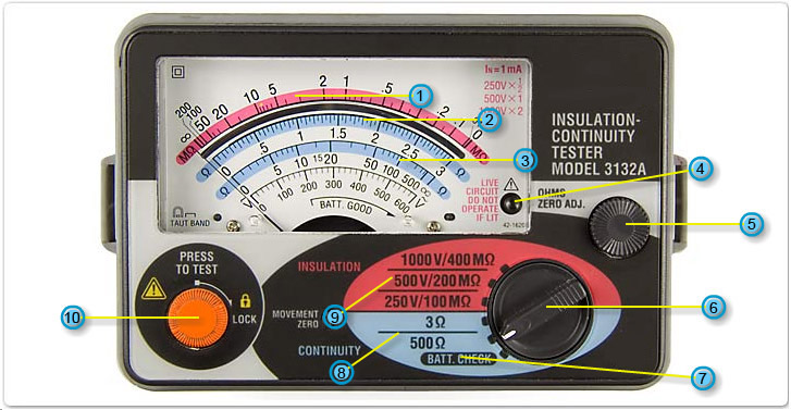
- Mega ohm scale Used to show mega ohm resistance values. When set to 250V/100MΩ - multiply reading by 1/2. When set to 500V/200MΩ - multiply reading by 1. When set to 1000V/400MΩ - multiply reading by 2.
- Ohm scale Displays resistance values up to 3Ω . Used when selector switch is on 3Ω position.
- Ohm scale Displays resistance values up to 500Ω . Used when selector switch is on 500Ω position.
- Light (LED) Warning light to indicate the circuit being tested is live.
- Ohms zero adjustment Used to ensure accuracy of meter readings. When a resistance scale is selected, touch meter leads together and turn the ohms zero adjustment so the needle is exactly positioned on 0 on the scale.
- Selector Allows user to select resistance range to be measured or battery check function.
- Battery check Allows user to check the condition of the internal battery of the meter. Condition is shown on bottom scale of the display.
- Continuity test positions Positions to allow measurement of up to 3 or 500Ω. Often used to check continuity of a circuit or conductor.
- Insulation test positions Measurement of insulation used in systems with the following approximate voltages. Use the 250V position for tests on 110V systems. Use the 500V position for tests on 240V systems. Use the 1000V position for tests on 440V systems.
- Test button When the meter is connected across the circuit to be tested, press the test button to observe the reading on the display. Keep button in lock position when meter is not in use.
3. Is the meter correctly set to measure the resistance of insulation used in a 240V electrical system?
- Yes
- No
Testing insulation
An insulation test should be conducted at twice the systems normal working voltage. Eg, a 110 volt system should be tested at 250 volts, a 240 volt system should be tested at 500 volts and a 440 volt system should be tested at 1000 volts.
4. What does it mean to calibrate the meter?
- Set to the highest settings
- Earth the meter
- Check accuracy and make precise adjustment
- Do a voltage drop test
5. How does an IR tester work?
- Uses resistive capacitance (RC) effect.
- Calculates the atomic structure (resistivity).
- Uses heat to determine resistance.
- Applies voltage, measures current then calculates resistance.
Where to use the IR tester
The IR tester can measure resistance in mega ohms, this is necessary when conducting insulations tests involving:
- conductors
- motors
- switchboards.
If you had trouble answering the questions about measuring resistance, get more information from:
- Electrical principles section in Resources
- text books
- internet sites
- your trainer.
Repeat this Reinforcement activity or move on to the activity on capacitance.
When you have finished:
- show your answers to your trainer
- close this window and choose a new activity from the menu.