Using meters
Instructions:
There are 21 questions:
For the multi-choice questions:
- choose the correct answer
- write down your answer.
For the meter reading questions:
- determine measured value
- specify the appropriate unit
- write down your answer.
Note:
You can print this page and write your answers onto it.
Question 1
The following image shows a specific type of meter/tester.
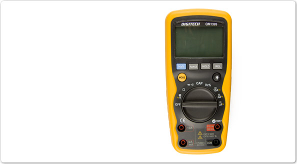
What type of meter/tester is it?
- Clamp meter
- IR meter (insulation resistance)
- LED voltage detector
- Multimeter (analogue)
- Multimeter (digital)
Question 2
The following image shows a specific type of meter/tester.
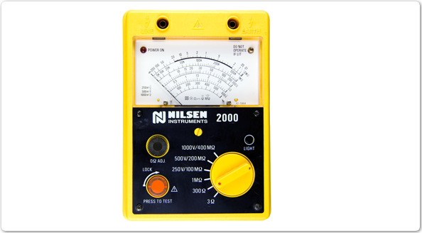
What type of meter/tester is it?
- Clamp meter.
- IR meter (insulation resistance).
- LED voltage detector.
- Multimeter (analogue).
- Multimeter (digital).
Question 3
The following image shows a specific type of meter/tester.
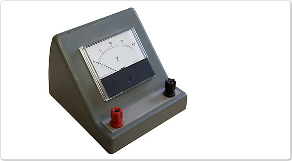
What type of meter/tester is it?
- IR meter (insulation resistance).
- Bench meter (voltage).
- LED voltage detector.
- Multimeter (analogue).
- Clamp meter.
Question 4
The following image shows a specific type of meter/tester.
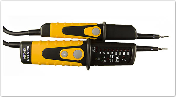
What type of meter/tester is it?
- IR meter (insulation resistance).
- Bench meter (voltage).
- LED voltage detector.
- Multimeter (analogue).
- Clamp meter.
Question 5
The following image shows a specific type of meter/tester.
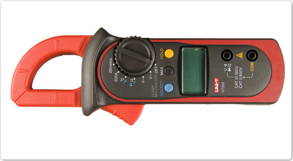
What type of meter/tester is it?
- Multimeter (analogue).
- Bench meter (voltage).
- LED voltage detector.
- Clamp meter .
- IR meter (insulation resistance).
Question 6
In which type of meter can parallax error occur?
- Analogue.
- Digital.
- Oscilloscope.
- LED voltage test meter.
Question 7
The following image shows a reading on the dial of an analogue multimeter and the function switch set to a specific position.
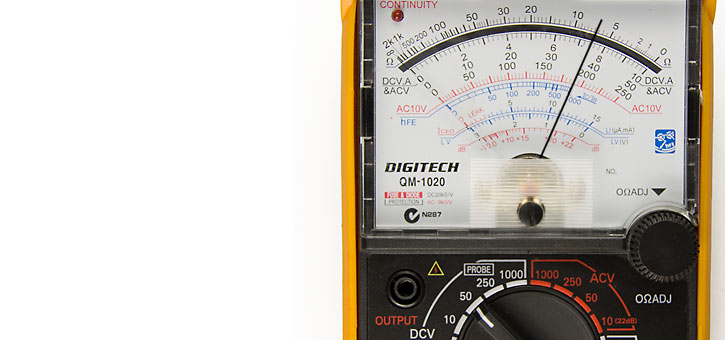
What reading is displayed on the meter?
Question 8
The following image shows a reading on the dial of an analogue multimeter and the function switch set to a specific position.
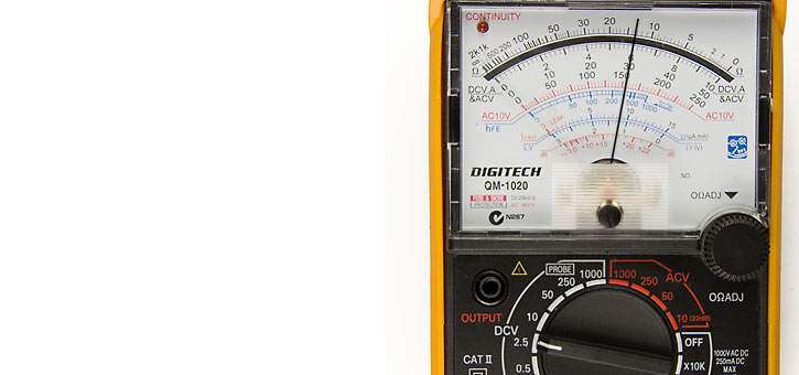
What reading is displayed on the meter?
Question 9
The following image shows a reading on the dial of an analogue multimeter and the function switch set to a specific position.
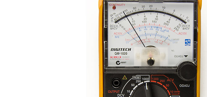
What reading is displayed on the meter?
Question 10
The following image shows a reading on the dial of an analogue multimeter and the function switch set to a specific position.
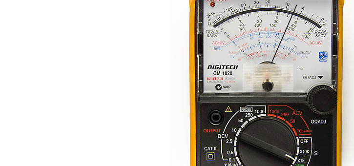
What reading is displayed on the meter?
Question 11
How must a bench type ammeter, as shown in the following diagram, be connected to a circuit to measure current flow?
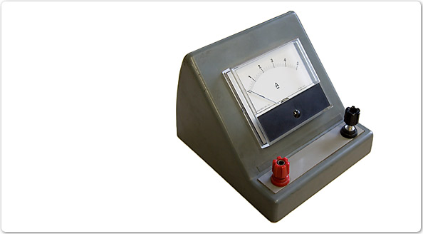
- Connected in parallel with the circuit.
- Connected in series with the circuit.
- Connected in series/parallel with the circuit.
- Clamps placed around current carrying conductor.
Question 12
How should the clamp type ammeter, as shown in the following diagram, be connected to a circuit to measure current flow?

- In parallel with the circuit.
- In series with the circuit.
- In series/parallel with the circuit.
- Clamps placed around current carrying conductor.
Question 13
How must a bench type voltmeter, as shown in the following diagram, be connected to a circuit to measure voltage?

- In parallel with the circuit.
- In series with the circuit.
- In series/parallel with the circuit.
- Clamps placed around current carrying conductor.
Question 14
When testing ohms with a digital multimeter how must it be connected to measure a circuit’s resistance?
- In parallel with circuit.
- In series with the circuit.
- In series/parallel with the circuit.
- Clamps placed around current carrying conductor.
Setting up a multimeter
In the next four questions you need to specify:
- which position the function switch should be set to
- which meter terminal the red probe leads should be connected to
- which meter terminal the black probe leads should be connected to.
The questions relate to a digital meter with the following features:
Choices for the function switch position:
- V~
- V–
- Ω
- Continuity
- nF
- uF
- Hz
- hFE
- uA
- mA
- A
Choices for the meter terminals:
- A (10A MAX)
- mACx (300mA MAX)
- COM
- VΩF
Question 15
Position the function switch, and connect the positive and negative probe leads to allow the multimeter to measure an expected value of half an amp.
- Function switch position set to?
- Red probe lead connected to?
- Black probe lead connected to?
Question 16
Position the function switch, and connect the positive and negative probe leads to allow the multimeter to measure an expected value of 12 volts.
- Function switch position set to?
- Red probe lead connected to?
- Black probe lead connected to?
Question 17
Position the function switch, and connect the positive and negative probe leads to allow the multimeter to measure an expected value of 8 amps.
- Function switch position set to?
- Red probe lead connected to?
- Black probe lead connected to?
Question 18
Position the function switch, and connect the positive and negative probe leads to allow the multimeter to measure an expected value of 100 ohms.
- Function switch position set to?
- Red probe lead connected to?
- Black probe lead connected to?
Question 19
The loading effect of a voltmeter connected in parallel with a component will cause what change to the circuit?
- Less current will flow.
- More current will flow.
- No current will flow.
- The same amount of current will flow.
Question 20
The internal resistance of an ammeter is:
- high
- low
- dependent on the circuit supply voltage.
Question 21
What will happen if an ammeter is connected in parallel with a circuit.
- Ammeter will read circuit current flow.
- Probable ammeter and wiring damage.
- Probable ammeter and motor damage.
When you have finished:
- show your answers to your trainer
- close this window and choose a new activity from the menu.