Parallel calculations
Following are information and questions on parallel circuits.
Instructions:
For the multi-choice questions:
- choose the correct answer
- write down your answer.
For the calculation questions:
- calculate the unknown value
- specify the appropriate unit
- write down your answer.
Note:
- You can print this page and write your answers onto it.
- You can use a calculator.
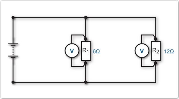
1. What voltage is applied to each of the resistors in a parallel circuit?
- Most voltage is applied to resistor 1 (R1).
- Most voltage is applied to resistor 2 (R2).
- The same voltage is applied to resistor 1 and resistor 2.
In a parallel circuit each resistor is connected directly to the voltage source, therefore the voltage across each resistor is the same, as shown in the following diagram.

2. Which of the following statements reflects Kirchoff's current law?
- Current leaving the supply is greater than returning current.
- Current leaving the supply is less than returning current.
- Current leaving the supply equals returning current.
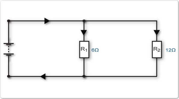
Current flow from the voltage source is always equal to the amount of current flow returning to the voltage source, as shown in the following diagram.

3. How will the current flow from the voltage source split to flow through each of the resistors?
- Most current will flow through resistor 1 (R1).
- Most current will flow through resistor 2 (R2).
- The same amount will flow through resistor 1 and resistor 2.
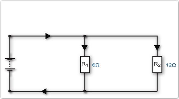
Current flow from the voltage source splits and flows through each of the resistors.
Most current will flow through R1. This is because R1 has the lowest resistance value and therefore the least opposition to current flow, as shown in the following diagram.
4. Calculate the current flow through R3 in this circuit.
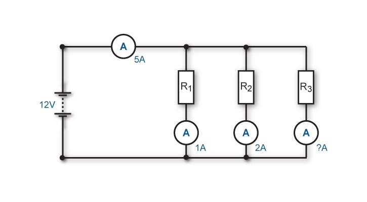
Total current flow in a parallel circuit equals the sum of the current flow through each resistor. This can be represented by the formula:

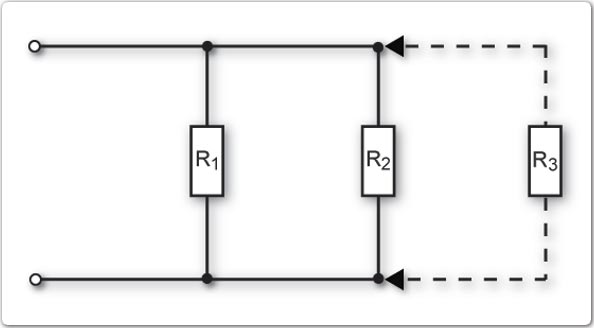
5. What happens to the total resistance of a parallel circuit if an additional resistor is added in parallel?
- Total resistance increases.
- Total resistance decreases.
- Total resistance remains the same.
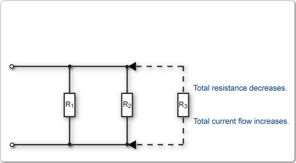
By adding another resistor in parallel we are providing an additional path for current to flow. The current flow from the voltage source will therefore increase. An increase in current from the source can only occur because the total resistance has decreased, as shown in the following diagram.
6. Which formula is used to determine total resistance of a parallel circuit?
- RT = R1 + R2 + R3
- 1/RT = 1/R1+ 1/R2 + 1/R3
- RT = R1 x R2 x R3
- 1/RT = 1/R1x 1/R2 x 1/R3
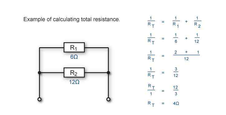
The formula below is one of a number of formulae that can be used to calculate total resistance of a parallel circuit. This formula can be used for any number of resistors and is valid whether each individual resistance value is the same or different.

7. Calculate the total resistance of this circuit
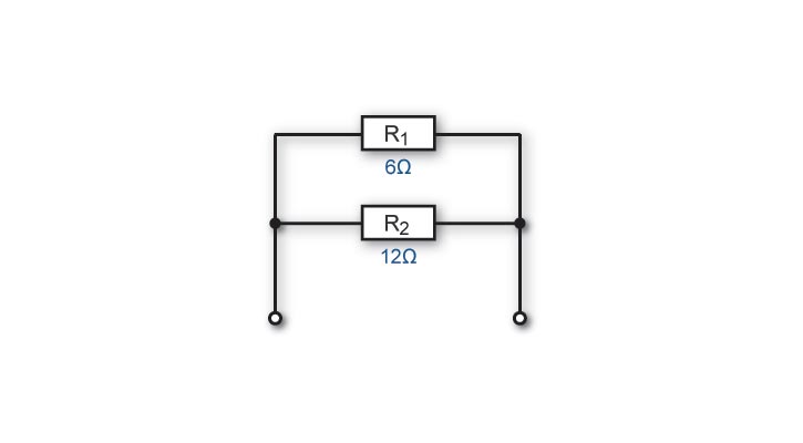
The following diagram shows an example of calculating total resistance in a circuit with two resistors connected in parallel.
Summary of parallel circuits:
- the voltage is the same across each resistor.
- current flow from the voltage source equals current flow returning to the voltage source.
- amount of current flow through each resistor depends on the resistor value.
- the sum of the current flow through each resistor equals the supply current.
- adding a resistor to a parallel branch decreases total resistance.
- the total resistance of a parallel circuit can be calculated using the following formula:

Knowledge of parallel circuits and Ohm's law will allow you to answer the following questions.
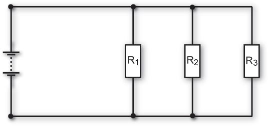
8. Calculate the total resistance of this circuit
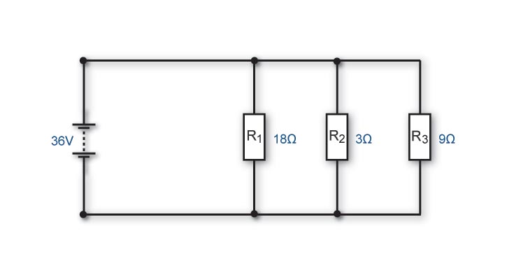
9. Calculate the voltage across R3 in this circuit.
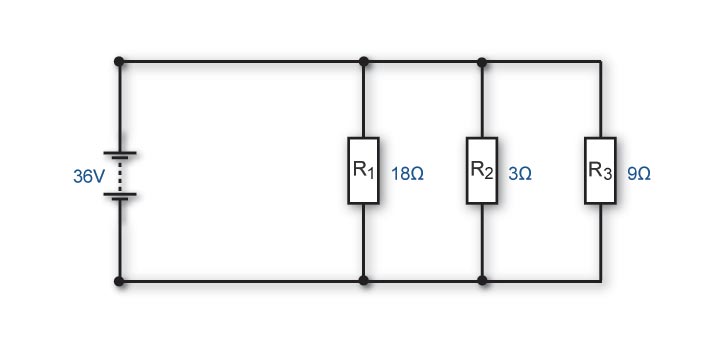
10. Calculate the current flow through R1 in this circuit.
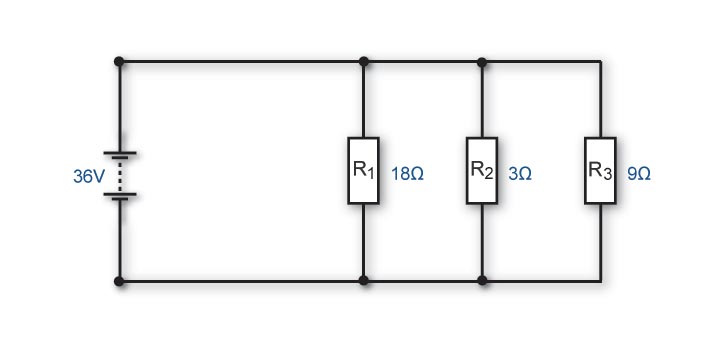
11. Calculate the current flow through R2 in this circuit.
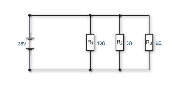
12. Calculate the current flow through R3 in this circuit.
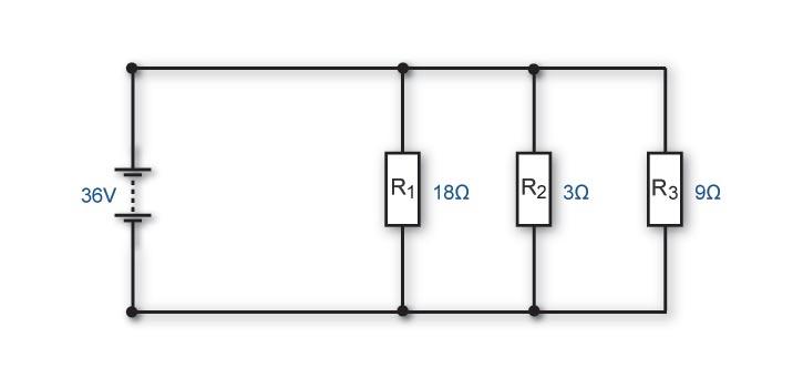
13. Calculate the total current flow in this circuit.
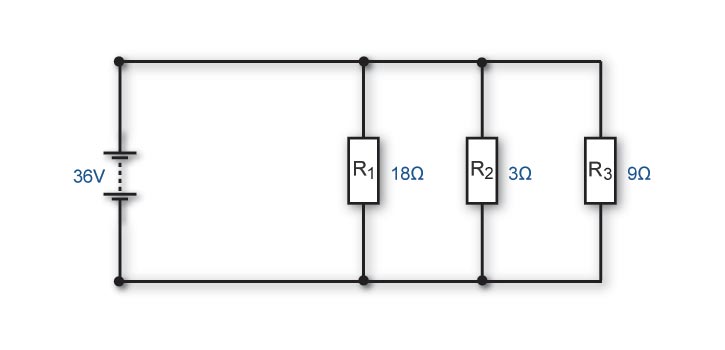
14. Calculate the resistance value of R2 in this circuit.
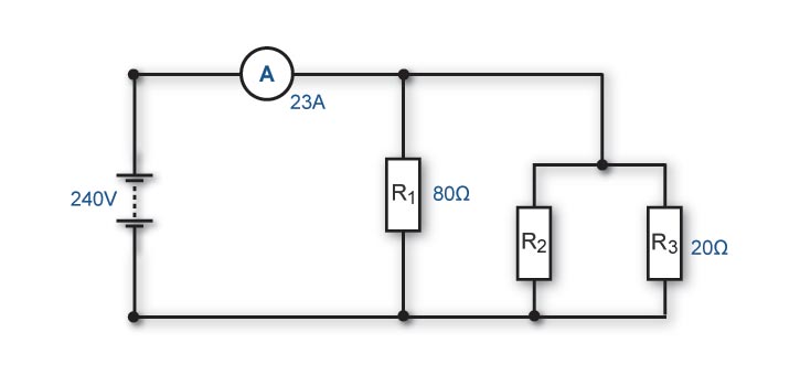
If you had trouble answering the questions about parallel circuits, get more information from:
Electrical principles section in Resources
- text books
- internet sites
- your trainer.
Repeat this Reinforcement activity or move on to the activity on circuit conditions.
When you have finished:
- show your answers to your trainer
- close this window and choose a new activity from the menu.