Parallel measurement
Instructions:
This activity has three sections:
- measure voltage
- measure current flow
- measure resistance.
Note:
- You can print this page and write your answers onto it.
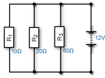
Parallel circuit diagram
Instructions:
- look at the circuit diagram
- observe voltage and resistance values
- print or draw the diagram for future reference.
Section 1 – Measure voltage
Instructions:
You'll be shown a connected parallel circuit. You'll need to:- answer questions about meter connection
- answer questions about voltage readings
- write down your answer.
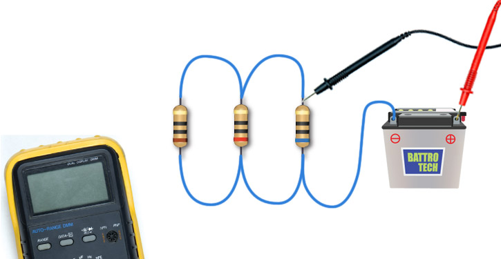
1. When using a multimeter for measuring voltage, what should you do?
- Check the circuit polarity.
- Connect the circuit to a power supply.
- Remove or isolate the power source.
- The first two answers are correct.
2. Select the meter reading you'd expect for this voltage test.
- 0.12 mV
- 12 KV
- 12 A
- 120 V
- 12 V
- 12 mΩ
- -12 V
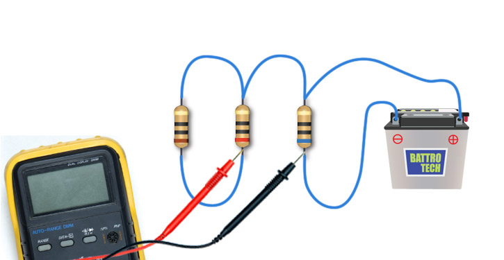
3. Select the meter reading you'd expect for this voltage test.
- 0.12 mV
- 12 KV
- 12 A
- 120 V
- 12 V
- 12 mΩ
- -12 V
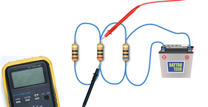
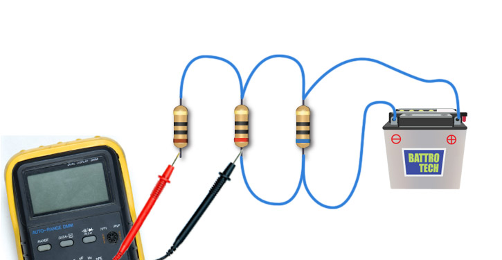
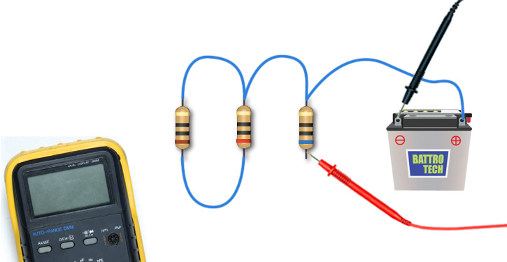
4. Will this connection show the voltage across R1?
- Yes
- No
5. What would voltage measurement across the three resistors determine?
- Voltage is the same across all resistors in parallel.
- Voltage is highest at the largest resistor.
- Voltage is lowest at the largest resistor.
Section 2 – Measure amperage
Instructions:
You'll be shown a connected parallel circuit. You'll need to:
- answer questions about using an ammeter
- answer questions about measuring amps at specific points in the circuit
- write down your answer.
Note:
- You can print this page and write your answers onto it.
6. When using a multimeter for measuring amperage, what should you do?
- Connect the ammeter in series with the circuit.
- Check the circuit polarity.
- Determine if the measurement will exceed the rating of the meter.
- All of the above are correct.
7. If a ten ohm resistor is connected to a twelve volt power supply, what range would you expect the amps to be?
- 0 to 2 amps.
- 0 to 1 milliamps.
- 10 to 20 amps.
- 0 to 10 amps.
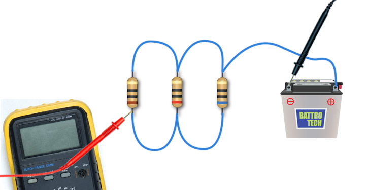
8. Will this connection show the current flow through R1?
- Yes
- No
9. Select the meter reading you'd expect for this current test.
- 0.2 A
- 0.8 A
- 1.8 A
- 1.2 A
- 2A
- 0.6A
- 0.002 mA
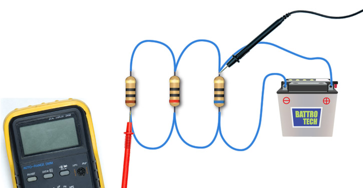
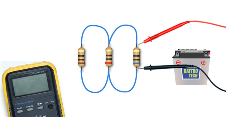
10. Would this ammeter connection show total current for the circuit?
- Yes
- No
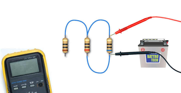
11. Would this ammeter connection show current flow through R1 only?
- Yes
- No
12. Would this ammeter connection show current flow through R3 only?
- Yes
- No
Section 3 – Measure resistance
Instructions:
You'll be shown a connected parallel circuit. You'll need to:
- answer a question about meter connection
- answer questions about measuring resistance at specific points in the circuit
- write down your answer.
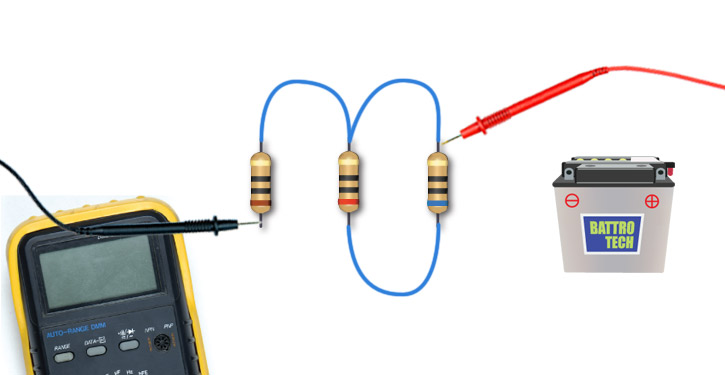
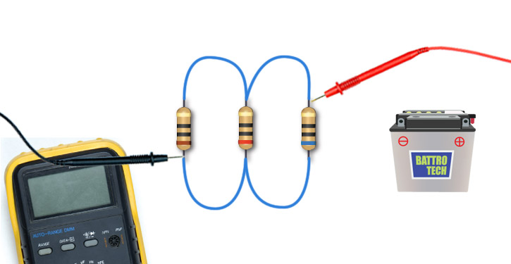
13. Before connecting a multimeter into a circuit for measuring resistance, what should you do?
- Bypass all resistances.
- Connect the circuit to a power supply.
- Remove or isolate the power source.
- Check the circuit polarity.
14. Select the meter reading you'd expect for this resistance test.
- 10 Ω
- 60 Ω
- 20 Ω
- 12 mΩ
- 6 Ω
- 0.2 Ω
- 90 Ω
- 1.2 Ω
- 0.6 Ω
15. Select the meter reading you'd expect for the resistance test shown.
- 10 Ω
- 60 Ω
- 20 Ω
- 12 mΩ
- 6 Ω
- 0.2 Ω
- 800 Ω
- 15 Ω
- 0.6 Ω
16. Would this ohmmeter connection show the resistance of R1?
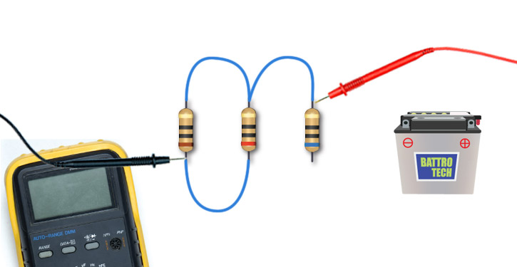
- Yes
- No
17. Would this ohmmeter connection show the resistance of R1?
- Yes
- No
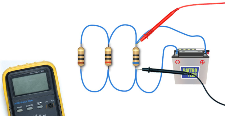
18. Would this ohmmeter connection show the resistance of R1?
- Yes
- No
19. What would you notice about the total resistance value in a parallel circuit?
- It would be higher than any individual resistance in the circuit.
- It would be equal to the sum of all of the individual resistances.
- It would be lower than any individual resistance in the circuit.
When you have finished:
- show your answers to your trainer
- close this window and choose a new activity from the menu.