Connection and measurement
Instructions:
For this activity you'll need to:
- connect a series circuit
- measure resistance
- measure voltage
- measure current flow.
To do this activity you'll need access to the following equipment:
- a multimeter
- a nine volt battery
- at least four jumper wires
- a selection of colour coded resistors rated at one watt .
Section 1 – Connect the series circuit
Instructions:
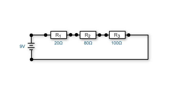
- Look at the circuit diagram as shown below.
- Select the three resistors by colour code to match ohm values shown on the diagram.
- Using the jumper wires, wire the components as shown on the diagram.
Get your trainer to check your work.

Section 2 – Measure resistance
Question.
Before connecting a multimeter to measure resistance in a circuit what should you do?
- Connect the circuit to a power supply.
- Remove or isolate the power source.
- Bypass all resistances.
- Check the circuit polarity.
The correct answer is number 2. The power source for the circuit must be removed or isolated otherwise the meter will be damaged.
Measurement instructions:
Using your connected series circuit. You'll need to:
- setup the multimeter to measure resistance
- disconnect the battery from the circuit
- measure and record resistance at the following points in the circuit.
- Measure the resistance of R1.
- Measure the resistance of R2.
- Measure the resistance of R3.
- Measure the total resistance of the series circuit.
Section 3 – Measure voltage
Question.
When using a multimeter for measuring voltage, what should you do?
- Check the circuit polarity.
- Connect the circuit to a power supply.
- Remove or isolate the power source.
- The first two answers are correct.
The correct answer is number 4. The power source for the circuit needs to be connected and you should observe the circuit polarity so that you connect the meter probes accordingly.
Measurement instructions:
Using your connected series circuit. You'll need to:
- setup the multimeter to measure voltage
- measure and record voltage at the following points in the circuit.
- Measure the supply voltage.
- Measure voltage drop across R1.
- Measure voltage drop across R2.
- Measure voltage drop across R3.
Section 4 – Measure amperage
Question 1.
When using a multimeter for measuring amperage, what should you do?
- Connect the ammeter in series with the circuit.
- Check the circuit polarity.
- Determine if the measure will exceed the meter rating.
- All of the above are correct.
The correct answer is number 4. When using an ammeter:
- it must be connected in series with the circuit
- the amount of current to be measured must be within the range of the meter, otherwise the fuse in the meter will be blown or the meter could be damaged
- it should be connected in correct polarity (red towards positive) to get the correct reading.
Question 2.
If a circuit has a total resistance of two hundred ohms and power supply of nine volts, what range would you expect the amps to be?
- 0 to 1 amps
- 0 to 1 milliamps
- 10 to 20 amps
- 0 to 10 amps
The correct answer is number 2. If you use Ohm's law you can calculate the current flow range expected for the circuit and it is 0.005 A (five milliamps).
Measurement instructions:
Using your connected series circuit. You'll need to:
- setup the multimeter to measure amperage
- measure and record the current flow in the circuit.
If you had trouble doing this challenge you should:
- choose Resources and look in the Electrical principles section to review information about these topics
- refer to other resources
- ask your trainer for help
- do the Reinforcement activity for more practice
- do this Challenge again.
When you have finished:
- show your answers to your trainer
- close this window and choose a new activity from the menu.