Scenario
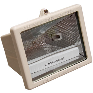
An electrician needs to fabricate a bracket to mount a floodlight to the fascia of a building. Based on measurements taken and information known the electrician chooses a particular design. Tools and equipment are not available to fabricate this bracket on site, therefore the electrician does a freehand drawing so that an engineering workshop can make the bracket. See below for details of the measurements taken and information known.
Measurements and information
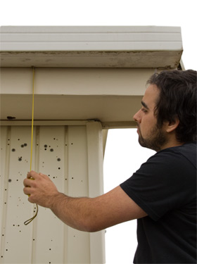
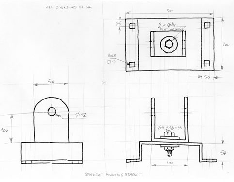
The electrician first takes some measurements on the job. The fascia is 300mm by 19mm timber and the mounting block on the back of the floodlight is 90mm wide with a 12mm bolt supplied. The bracket needs to be fabricated in such a way that the light can be adjusted vertically and horizontally. The electrician decides on a 'hat section' for the mounting plate, to be bolted to the fascia using cup bolts. To mount the floodlight a 'U' shaped bracket is bolted with a single 14mm bolt to the fascia plate will allow the light to pivot. The size selected for the fascia plate is 300mm wide by 200mm deep with a set out of 50mm. The light mounting bracket is to be made from 50mm wide flat steel. Both the plate and bracket are to be fabricated from steel 3mm thick.

Freehand drawing
The following series of images and text show and describe the development of the freehand drawing.
Step 1
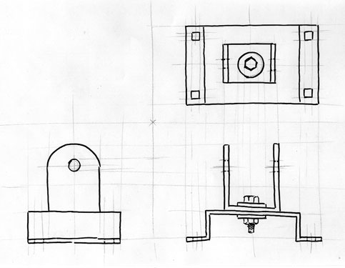
Light guide lines, including centre lines, are drawn onto the paper in proportion to the size of the fascia mount. These are drawn to allow for front, side and top views in third angle projection.

Step 2
The outline of the 'hat' shaped fascia mount is then drawn using the guide lines for reference. Choose next to see step three of the drawing.

Step 3
Now the outline for the 'U' shaped bracket is drawn using the centre lines and guides as reference. Choose next to see step three of the drawing.

Step 4
Now details of the 14mm centre pivot bolt and 12mm light mounting hole are added. Choose next to see step three of the drawing.

Step 5
Square holes are drawn onto the fascia plate to allow mounting to the fascia board. Square holes are used to accommodate cup head bolts. While the fabrication of the square holes is more time consuming than round holes, the use of cup head bolts will have two advantages; they provide a flush finish, and don’t require a second spanner when being tightened. Choose next to see step three of the drawing.

Step 6
The final step is to add the dimensions and labels to the diagram. The finished diagram should have sufficient information to enable any worker to be able to manufacture the product.

Use this link to see a full size version of the finished freehand drawing in Word (99kb) .
